บทความก่อนหน้าเรื่อง จำลองการทำงาน DC Motor ในรูปแบบสมการเสตท (State Equation) โดย Matlab เราได้ศึกษาการเขียนสมการพลศาสตร์ของดีซีมอเตอร์ ในรูปบบสมการเสตท ไปแล้ว
ในบล๊อกนี้เราจะเรียนรู้วิธีการออกแบบตัวควบคุม เพื่อให้ดีซีมอเตอร์มีผลตอบสนองในแบบที่เราต้องการ ซึ่งเราทราบว่าผลตอบสนองของระบบ เช่น ค่า Over shoot , Settling Time มีความสัมพันธ์โดยตรงกับตำแหน่งโพลของระบบ ดังนั้นหากเราสามารถกำหนดตำแหน่งโพลให้แก่ดีซีมอเตอร์ได้ ก็หมายถึงเราสามารถกำหนดผลตอบสนองของดีซีมอเตอร์ได้นั้นเอง
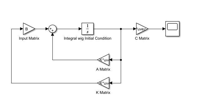
Pole Placement เป็นวิธีการกำหนดตำแหน่งโพลที่เราจะศึกษากันในบทความนี้ State Space Feedback สามารถแสดงได้ดังรูปที่ 1
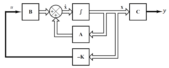
จากรูปที่ 1 เขียนเป็นสมการได้ดังนี้
(1)
โดยกำหนดให้
(2)
จากสมการ (1) และ (2) สมมติว่าระบบที่เราจะออกแบบตำแหน่งโพลมีค่า A, B และ K ดังนี้
หากเราต้องการออกแบบระบบให้มี pole อยู่ในตำแหน่ง -1 และ -2 นั้นหมายความว่าระบบจะต้องมีสมการคุณลักษณะเฉพาะดังนี้
(3)
จัดรูปสมการ (3) จะได้
(4)
แทนสมการ (2) ลงในสมการ (1) จะได้
(5)
สมการคุณลักษณะเฉพาะของระบบ State Space หาได้จาก
(6)
แทนค่า A, B และ K ลงในสมการ (6)
(7)
ทำการดีเทอร์มิแน่น สมการ (7) จะได้
(8)
เปรียบเทียบสมการ (8) และ (3) จึงสรุปได้ว่าการกำหนดค่า \(k_{1}\) และ \(k_{2}\) ที่เหมาะสม จะทำให้ได้ตำแหน่งของโพลตามกำหนดในสมการ (3) นั้นเอง เราเรียกวิธีนี้ว่า Pole placement
เราจะทดสอบการวางตำแหน่งโพลที่เราต้องการโดยจำลองการทำงานบนโปรแกรม Matlab/Simulink โดยการสร้างคอนโทรลบล๊อกไดอะแกรมดังภาพ
จากแบบจำลองของ State Space DC Motor ที่เราสร้างขึ้น หากเราต้องการให้ Maximum Overshoot = 33% และ Settling Time = 17 Sec. จะได้ว่า DC Motor ควรจะต้องมีโพลอยู่ทีตำแหน่ง -0.2353 + 0.6667i และ -0.2353 – 0.6667i (Matlab Script ทำการคำนวณให้อัตโนมัติ) ให้ทำการรัน Script ดังนี้
%% State feedback control design
clear
close all
clc

%% Problem: Design state feedback control for DC Motor
% Motor parameters
R=0.5;                  % Armature Resistance (ohm)
L=0.2;                  % Armature inductance (H)
Kt=0.929;               % Torque Constant (Nm/Amp)
Kb=0.929;               % Back emf Constant (V.s/rad)
J=3;                    % Moment of inertia (kg.m^2)
b=0.0408;               % Friction Constant (Nm.s/rad)
V=200;                  % Armature voltage (V)

%% State-model of DC motor (Physical variable form)
A=[-R/L -Kb/L;Kt/J -b/J]   % System matrix
B=[1/L;0]                  % Input matrix
C=[0 1]                    % Output matrix
D=0;                        % Direct transmission matrix

%% Initial conditions
x0=[0; -1];                 % Arbitrary initial conditions

%% Checking eigenvalues
E=eig(A);                   % Just to check stability and pole locations

%% Checking controllability
Qc=ctrb(A,B);               % Needed for feedback control design
R=rank(Qc);

%% Desired locations of the poles


M=33;                            % Desired Maximum Overshoot
Ts=17;                           % Desired Settling time

d=Ts;
h=(-log(M/100))^2;
zeta=sqrt(h/(pi^2+h));          % Damping ratio

wn=4/(Ts*zeta);                 % Natural frequency

P=roots([1 2*zeta*wn wn^2])    % Desired Poles result

%% Checking the system response
num=wn^2;
den=[1 2*zeta*wn wn^2];
G=tf(num,den);

figure(1)
step(G)
grid on
xlabel('Time')
ylabel('Amplitude')
title('Response of Desire Poles Location')
S=stepinfo(G);                  % Check this is matching with M and Ts or not

%% State feedback by pole placement
K=place(A,B,P)                 % Pole placement

sys=ss(A-B*K, eye(2), eye(2), eye(2));
                                % Closed-loop system
t=0:0.01:d*2;                  % Time for plotting response
x= initial(sys,x0,t);
x1=[1 0]*x';                    % Current
x2=[0 1]*x';                    % Speed

figure(2)
subplot(2,1,1);
plot(t,x1), grid
xlabel('Time (s)')
ylabel('Current')
title('State Pole Placement Response of current to Initial Condition')

subplot(2,1,2);
plot(t,x2),grid
xlabel('Time (s)')
ylabel('Speed')
title('State Pole Placement Response of speed to Initial Condition')

%% Simulink model simulation (It will give same results)
sim('DC_Model')            % Check simulation results

% Results can be plotted here also by writing some more commands
% Check overshoot and settling time of response of speed. It must be same
% as designed.
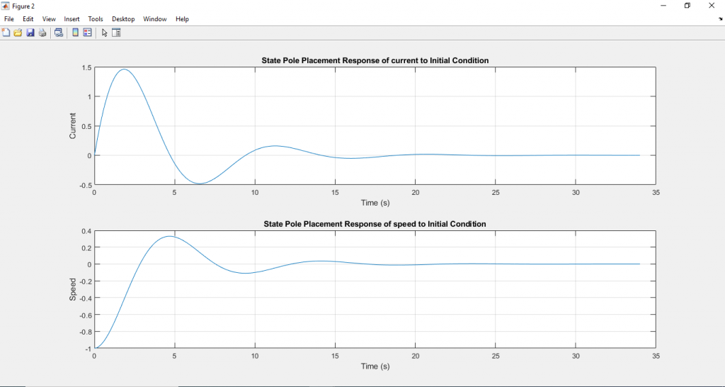
จากการคำนวณของโปรแกรม Matlab เราจะทราบว่าค่า K จะเท่ากับ -0.4086 และ -0.6101
นำค่า K ทั้งสองค่ามาใช้ในการป้อนกลับสัญญาณ จะทำให้ DC Motor มีโพลตามตำแหน่งที่ต้องการ จากแบบจำลองที่สร้างขึ้นในโปรแกรม Simulink จะให้ผลลัพธ์
ดาวน์โหลด Matlab/Simulink ไฟล์ได้ที่นี่